Detailed software design in the software lifecycle
In this lecture we'll contextualize the role of coding as only one activity in the software development process and walk through the software-lifecycle as an accountable path toward a reliable software product.
Lecture upshot
Coding is only one activity in the software developmemnt process. The engineering activity starts earlier and ends later.
The Software Development Lifecycle (SDLC)
So far we've mostly reduced software development down to "coding".
- However, with maven's packaging phase we've also seen how software must also perform outside the IDE (a software deliverable musts work outside the IDE)
- Ultimately, we're building software not for us (the developers), but for users.
- So ideally what we delivered at the end of the day conforms perfectly to user needs.
Nailing Skyjo is relatively easy:
- You have the ruleset: The requirements are already more or less set in stone and pretty clear.
- You have parts of the solution: Graphics, user interaction, etc.
- You have interfaces that guide your implementation.
Software engineering novices often confuse software engineering with just coding. But most software projects start a lot earlier, and end far later...
Software engineering is more about humans than code.
To begin with, users don't always know what they want. In fact, most of the time they don't. It is our job as software engineer to make sense of their (often) confusing, chaotic, or contradicting explanations, and nonetheless build something that meets their requirements.
Software lifecycle definitions
- (Detailed) software design is only one activity when it comes to developing software.
- Before we dive into hands-on design decisions, let's take a brief look at the terminology
- Software lifecycle: phases a software product goes through from initial idea to retirement
- Software process: structured set of activities and practices followed to produce software (the methodology)
Ian Sommerville says: A software process is a sequence of activities that leads to the production of a software product. There are four fundamental activities that are common to all software processes. These activities are:
- Software specification, where customers and engineers define the software that is to be produced and the constraints on its operation.
- Software development, where the software is designed and programmed.
- Software validation, where the software is checked to ensure that it is what the customer requires.
- Software evolution, where the software is modified to reflect changing customer and market requirements.
Info
In this lecture we're mostly focusing on the second point, i.e. we assume the requirements are sufficiently specified, and we do not bother with validation or maintenance. Depending on which software process is followed, these activities are not necessarily entirely separated.
Popular models
The most popular models, waterfall and agile walk through the activities defined by Sommerville. For example the waterfall model, as well as the iterative model set on five minimum phases:
1. requirement analysis
2. conceptual design
3. implementation
4. testing
5. maintenance

Note: The waterfall model appears strictly linear, but occasional revisions to previous activities are considered.
Requirement analysis
- Ideally the firsts stage is always obtaining an accurate understanding of what is actually wanted.
- Unfortunately, often enough this stage is either skipped altogether, or not follows thoroughly enough.

Requirement analysis is essential
Beginning to code without a clear understanding of user requirements is one of the most effective ways to waste resources and fail a software project.
Textual use cases
Textual use cases are a written description of success scenarios. They describe in which order actors (users, components) interact with one another, to gradually lead to a desired outcome.
Textual use cases contain (commonly) the following sections:
- ID, Name, Primary actor
- Goal
- Preconditions
- Main flow
- Postconditions
- Alternate flow
- Exceptions
Usually there's more than one
Typically, systems are too complex to be described by a single use case scenario. In that case use cases form a hierarchy from higher-level use cases, to referenced lower-level use cases, which in total form an accurate description of how the system is used.
Example: Automated Cat Feeding Device
Here's a common problem of cat owners. Our felines need to be fed every day, but somtimes we're out of town ( conferences, treehouse trips, etc...). Unfortunately we cannot just leave a mountain of cat-food, because our beloved pets are a bit overweight and tend to eat more than they should.

Keksli. Cute, but does not know his limits. If left with a mountain of cat food, he'll just eat everything... and then bad things will happen.
Here is a description of a success scenario for a system to alleviate the issue:
  Use Case ID: ACFD-01
  Use Case Name: Schedule Cat Feeding
  Primary Actor: User

  Goal:
  To ensure the cat receives food automatically after a set countdown, even when the user is not home.

  Preconditions:
  - The A.C.F.D. is powered and operational.
  - The Food Bay is empty or ready to be refilled.
  - The User has access to the Control Panel.

  Main Flow:
  1. The User fills the Food Bay with food.
  2. The User closes the Food Bay, ensuring the open status is “closed.”
  3. The User sets a countdown time for release using the Control Panel.
  4. The Control Panel sends the set time to the Display, which records the current time active value.
  5. The Display updates the Control Panel with the countdown status as time progresses.
  6. When the countdown reaches zero, the Control Panel triggers the Motor to drive the release mechanism.
  7. The Motor changes the open status of the Food Bay to “open.”
  8. The Cat, now able to access the food, empties the Food Bay by eating.

  Postconditions:
  - The Food Bay becomes empty.
  - The open status remains "open" until manually reset by the User.
  - The Cat’s hunger level  is assumed satisfied.

  Alternate Flow (Manual Abort):
  - At any time before countdown completion, the User can read the Display and cancel or adjust the timer via the Control Panel.

  Exceptions:
  - If the Food Bay is not properly closed, the Control Panel does not allow the timer to start.
  - If the Motor fails, the open command does not execute, and the User must intervene manually.
Which concepts are defined, and how do they relate to the main flow ?
- Concepts are: User, Food Bay, Control Panel, Display, Motor, Cat
- Each item in the main flow must declare one interaction between two components.
Domain model
- Domain models are extracted from use cases, i.e. they are a visualization of the concepts listed in the textual use
case description.
- Actors
- Components
- Domain models relate concepts based on their interaction, i.e. there are no functions defined in concepts, we only
list "what concepts want from another" to form relations. These relations define:
- Concern: what is requested
- Direction: who requests, who provides
- Multiplicities: how many instances per one instance
Relations example
From a use case model for exam writing we could infere that professors create exams and students take them. In terms of concepts and multiplicities this translates to:

Domain model example: Automated Cat Feeding Device
Based on the previous ACFD use case description, we can extract the following concepts and relations, to build a domain model:

Note: empty diamonds signify an "aggregation", that is the target component belongs to the source component, and cannot exist alone.
So far not many technical details
Keep in mind that the purpose of a domain model is to capture and understand system requirements. At this point we do not want to include solution relevant technical detail, e.g. if the user interacts with the control panel via buttons, how many buttons are needed, how many segments are needed for the display, etc... we do not add components beyond what is specified in the textual use case description.
OO software design
Once the requirements are formalized, you can pass to thinking about conceptual solutions.
Sets you on course for implementation
Diagrams set you on course for a successful implementation. With the digrams on point, implementation is a straighforward task. It is faster to make fundamnetal decisions (and spot bad decisions) on paper, in early stages, compared to implementing out entire classes only to realize that the solution is overly complicates (or cannot possibly work). Design happens on paper, not in the IDE.
- Although this phase is closer to code, this does not yet mean opening up an IDE and starting to write your software.
- Before you loose time with implementing code you might not need, place your attention on design decisions, notably:
- Datastructures
- Information encoding (Objects vs primitives)
- Class hierarchies, interfaces and abstract classes
- Object creation strategies
- Immutable vs Mutable objects
- Ideally, the outcome of this phase provides your with two implementation-relevant model types:
- Class diagrams: Which classes are required, what methods they offer, how they reference one another.
- Sequence diagrams: How methods work internally to provide a specific functionality.
Design choices are by definition conscient decisions
Design choices are based on facts and reasoning. Clear flaws, e.g. missing documentation, poor programming style, etc. are not design decisions.
Catching structural design with class diagrams
Class diagrams define how requirement concepts provide to solution concepts, which functionality is provided by each solution component, and how they relate to one another, in terms of dependencies and class hierarchies. In detail:
- For classes:
- their fields
- their methods
- whether static or not
- whether class, interface, or abstract
- For relations:
- Inheritance
- Dependencies
- Compositions
- Aggregations
Anything missing for an implementation ?
Yes! Class diagrams tell us nothing about behaviour, that is, we know which methods exist, but we do not know how they work.
Example: Zoo
- We are to implement a textual voice imitator system for a zoo, i.e. we want a small program that outputs the sound of a given animal.
- For instance if presented with an
Tiger, the system should outputRrrrroarrr!. We don't know how many animals are around, or which ones exactly.
An example for a design decision in this case are type-checks versus polymorphism.
- To keep things extensible, it could make sense to store animals in a
Set. - If there are thousands of animals, we could modularize comportment, i.e. avoid having one
if/else-ifsequence. - Instead of manual class-checking, we could use polymorphism.
- However, polymorphism also means adding more classes, and if we know from our requirements that there will only be two animal types, avoiding polymorphism could be a meaningful design decision.
Option 1: string map
The structural layout for a string check solution can be expressed as follows:
classDiagram
    class Launcher {
    }

    class Zoo {
        -animals: Map<string, string>
        +addAnimal(type: string, sound: string)
        +getSoundForType(type: string): string
    }

    Launcher "1" *--> "1" Zoo
Option 2: Polymorphism
The structural layout for a polymorphic solution can be expressed as follows:
classDiagram
    class Launcher {
    }

    class Zoo {
        -animals: Map<string, Animal>
        +addAnimal(name: string, a: Animal)
        +getSoundForType(type: string): string
    }

    class Animal {
    <<Interface>>
        +makeSound(): string
    }

    class Tiger {
        +makeSound(): string
    }

    class Lion {
        +makeSound(): string
    }


    Animal <|-- Tiger
    Animal <|-- Lion

    Launcher "1" *--> "1" Zoo
    Zoo "1" *-- "1..*" Animal
Note: Unfortunately, multiplicities have limited support in the diagram formated used here.
Capturing behavioural design with sequence diagrams
To truly capture all design decisions necessary for an implementation, we also need to specify method functioning, that is "what happens inside a method".
- This is done using sequence-diagrams, i.e. clear definitions of who-calls-who, and what potential calls are required inside a method.
- Let's illustrate the diagram format by formalizing what should happen within the
getSoundForTypemethod of either implementation.
Option 1: String map
sequenceDiagram
    participant L as Launcher
    participant Z as Zoo
    participant M as animals: Map<string, string>

    L->>Z: getSoundForType("tiger")
    activate Z
    Z->>M: get("tiger")
    activate M
    M-->>Z: "Roar!"
    deactivate M
    Z-->>L: "Roar!"
    deactivate Z
Reading the diagram from top to bottom, and left to right, following each method call, gives us an accurate understanding of how each method functions internally.
- Method execution is illustrated by a grey box.
- Calls are black arrows (carrying target function and arguments)
- Returns are dashed arrows (carrying result values)
Option 2: Polymorphism
sequenceDiagram
    participant L as Launcher
    participant Z as Zoo
    participant M as animals: Map<string, Animal>
    participant A as Animal (Tiger/Lion)

    L->>Z: getSoundForType("tiger")
    activate Z
    Z->>M: get("tiger")
    activate M
    M-->>Z: Animal (Tiger)
    deactivate M
    Z->>A: makeSound()
    activate A
    A-->>Z: "Roar!"
    deactivate A
    Z-->>L: "Roar!"
    deactivate Z
This second diagram reveals that the first solution is simpler, since there is no need for polymorphism if we just store all animal sounds in a map directly.
Testing
Software can be tested in many ways, but commonly we distinguish by scope (or horizon), i.e. "what to test":
| Horizon | Test type | Example |
|---|---|---|
| Isolated module | Unit-Test | Calling java class with input x returns y. |
| Interplay of multiple modules | Integration tests | System sends email to alert@uqam.ca when critical condition arrives. |
| Interplay of entire system | System test | Click on accept finalizes flight booking and generates boarding pass PDF` |
| Non functional aspect | Acceptance test | System reacts sufficiantly fast for productive use. |
In general
In general things get more difficult (and expensive) to test, the greater the horizon. E.g. unit tests are not expensive compared to hiring test users that attempt to interact with your system.
Testing and earlier phases
Even without an implementation, early software development lifecycle phases lay the groundwork for testing. Requirement analysis and design elicitation define:
- What methods are required.
- What comportment is expected.
Using these two, we can actually define unit tests before having an implementation. This practice is also referred to as "Test driven development".
Example
For a prime-checker, we can create a unit tests, to verify outputs for specific inputs:
import static org.junit.Assert.assertFalse;
import static org.junit.Assert.assertTrue;

import org.junit.Test;

public class PrimeCheckerTest {
  private final PrimeChecker checker = new PrimeChecker();

  /**
   * Tests if the number 23 is correctly identified as a prime number.
   */
  @Test
  public void testIsPrime23() {
    assertTrue(checker.isPrime(23));
  }
}
A developer can use the test method as grounds for method signatures and advancing a reliable implementation.
Beware of test hacking
Fullfilling tests is no guarantee for correctness, if you do not trust a developer, do not hand out all tests beforehand - they might hack the results aroung your tests.
Maintenance
Although maintenance is not handled in more depth in this course, keep in mind that the software lifecycle does not end with delivering a software to the client.
Even if the software is perfect at the moment of delivery, the job is not done, because the environment constantly evolves:
- The JDK may change, method may be deprecated or found insecure.
- The hardware may change, new incompatible CPUs may replace the current.
- And the worst... requirements may change (migrating old software is crazy expensive)
pie title Cost illustration of SDLC phases
"Requirement" : 3
"Design" : 8
"Implementation" : 7
"Testing" : 15
"Maintenance" : 67
On an average, the cost of software maintenance is more than 50% of all SDLC phases.
What about architectures ?
In the course layout we went directly from requirement analysis to OO design. Often times design also involves macro-structures, also called "software architecture" choices.
To clarify the distinction:
- OO design is about individual classes, their functions, their relations.
- Architecture is about macro-concerns:
- What larger components are in a system (e.g. packages)
- How does information flow between these components, are there restrictions
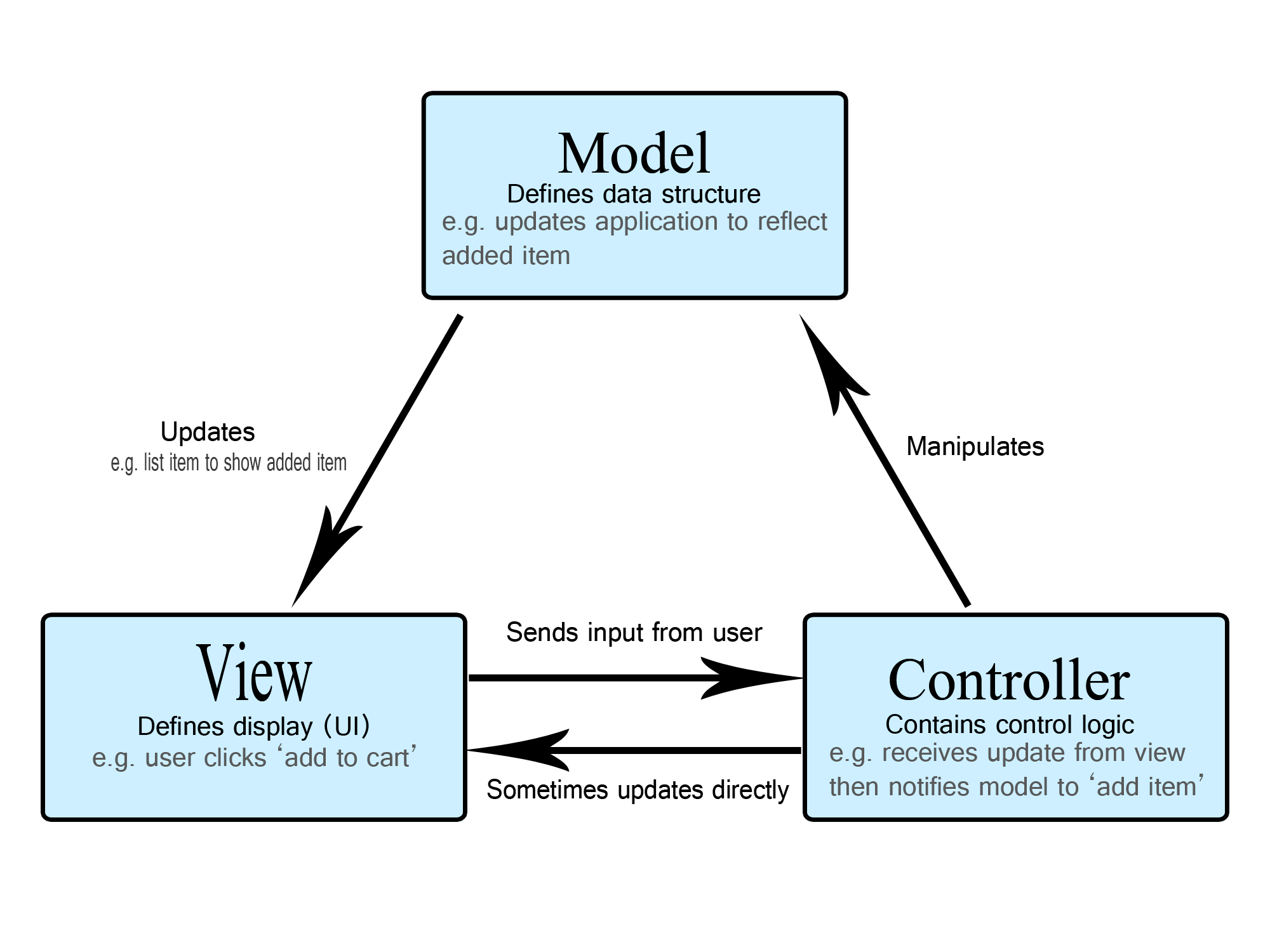
Model, View, Control
An example seen in class is MVC. MVC as is an architectural pattern (or style), dividing the software into three conceptual units:
- Model: for representing system state
- Controller: for transferring system state in a sane way, so the model is never corrupted / in an inconsistent state.
- View: To represent model state and consume user interactions, map them to controller actions
The main interest of MVC is to provide protection for applications. Intuitively you could tend to implement any system just with a UI and a Model. That is possible, but then you have zero integrity protection:
- Anyone can change anything.
- Programming errors in the UI likely corrupt your application state. Just think of a bank implementation, where all clients have full database access and are trusted to correctly handle currency in your model...
MISC
To conclude the lecture, here a few philosophical considerations for accountable software engineering.
On the role of requirements
Engineering is all about meeting the requirements:
- The product must meet the requirements (not the other way round).
- If the product does not meet the requirements, the engineers failed their job.
If you only know a hammer, everything looks like a nail.
Unfortunately inexperienced engineers tend to often think "solution first", rather than "problem first":
If the only tool you know to use is a hammer, everything looks like a nail to you.
Why engineering is not trivial:
- You must understand the requirements:
- Read and listen carefully.
- Be empathetic and anticipate needs.
- You must be able to select the most appropriate tool:
- Know more than one tool.
- Understand which contexts each tool fits best.
- Compare the problem context to the available tools.
- Manage trade-offs.
- Know how to effectively use the chosen tool.
Engineering is about trade-offs
There is rarely a single perfect solution. Engineering is about understanding and balancing risks, while keeping the focus on what matters most. Non-technical constraints such as time and budget often play a significant role as well.
Poor engineering
Engineering is about taking accountability for a software product:
- If there is no need for accountability, then there is no need for an engineer.
- As a software engineer, the value you bring to a company, is the liability you take for your code.
No-one, really no-one needs an engineer, who:
- Chooses a solution without thinking about alternatives.
- Copy-pastes code (a solution) without knowing how it works.
- Using an LLM to generate code that you do not understand, and just hits "run" until things seemingly "work"
... this is not engineering, this is programming by trial and error.
However, it is ok to use modern solutions, if you can take accountability:
- It is ok to use external tools, IDEs, modelling tools, etc.
- It is ok to search code examples online.
- It is ok to ask an LLM. (side mark: senior developers who use LLMs, tend to experience performance losses.)
- It is not ok to paste code that you do not 100% understand. You are liable for every line of code you use.
Don't rely on generative AI for critical decisions
Generative AI, especially LLMs operate on language models that complete provided text with what statistically often correlates.
To paraphrase what this means :
- AI tools have no cognitive understanding of the problem domain. Instead they wrap existing context with plausible sounding completions - for humans, we call this practice "bullshitting".
- Hallucination as a concept is not new, only the term, as a new euphisms for what we used to call a software bug: An inherent flaw that causes a software to be non-trustworthy.

Literature
Inspiration and further reads for the curious minds: